Lattice elements have to be used with material models describing the constitutive behaviour in the form of vector of tractions and rotational stress components, and strains and rotational strain components determined from displacement jumps smeared out over the element length.
This is a linear elastic material used together with lattice elements. It uses a stress strain law of the form
| (265) |
where σ is a vector of tractions and rotational components, and ε is a vector of strains obtained from displacement jumps smeared over the element length and rotational components. Furthermore, De is the elastic stiffness matrix which is based on the elastic modulus of the lattice material E, and a parameter a1 which is the ratio of the modulus of the shear and normal direction. There is the option to include a rotational stiffness. The model parameters are summarised in Tab. 56.
| Description | Linear elastic model for lattice elements |
| Record Format | latticelinearelastic (in) # d(rn) # [ talpha(rn) #] [ calpha(rn) #] e(rn) # [ a1(rn) #] [ a2(rn) #] |
| Parameters | - material number |
| - d material density |
|
| - [talpha] Thermal strain expansion coefficient. Default is 0. |
|
| - [calpha] Thermal displacement expansion coefficient. Default is 0. |
|
| - e Young’s modulus of the equivalent lattice material |
|
| - [a1] ratio of shear and normal modulus. Default is 1. |
|
| - [a2] ratio of rotational and normal modulus. Default is 1. |
|
| Supported modes | 2dlattice, 3dlattice |
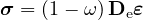
This is a scalar damage material model used together with lattice elements. It uses a scalar damage model, which results in a stress-strain law of the form
| (266) |
where σ is a vector of tractions and rotational components, and ε is a vector of strains obtained from displacement jumps smeared over the element length and rotational components. Furthermore, ω is the damage variable varying from 0 (undamaged) to 1 (fully damaged). Also, De is the elastic stiffness matrix which is based on the elastic modulus of the lattice material E, and a parameter a1 which is the ratio of the modulus of the shear and normal direction. The strength envelope (onset of damage) is elliptic and determined by three parameters, ft, fq and fc. The evolution of the damage variable ω is controlled by normal stress-normal crack opening law. The three possible laws are linear, bilinear and exponential.
This simple damage material model for lattice elements has been used in many recent articles. For instance, the two dimensional version has been used in P. Grassl and M. Jirásek. ”Meso-scale approach to modelling the fracture process zone of concrete subjected to uniaxial tension”. International Journal of Solids and Structures. Volume 47, Issues 7-8, pp. 957-968, 2010. An example of an application of the three dimensional version of the model is found in P. Grassl, J. Bolander. ”Three-Dimensional Network Model for Coupling of Fracture and Mass Transport in Quasi-Brittle Geomaterials”, Materials, 9, 782, 2016.
The model parameters are summarised in Tab. 57.
| Description | Scalar damage model for lattice elements |
| Record Format | latticedamage (in) # d(rn) # [ talpha(rn) #] e(rn) # [ a1(rn) #] [ a2(rn) #] [ e0(rn) #] [ coh(rn) #] [ ec(rn) #] [ stype(rn) #] [ wf(rn) #] [ wf1(rn) #] |
| Parameters | - material number |
| - d material density |
|
| - [talpha] Thermal strain expansion coefficient. Default i 0. |
|
| - [calpha] thermal displacement expansion coefficient. Default is 0. |
|
| - e normal modulus of lattice material |
|
| - [a1] ratio of shear and normal modulus. Default is 1. |
|
| - [a2] ratio of rotational and normal modulus. Default is 1. |
|
| - e0 strain at tensile strength: ft∕E |
|
| - coh ratio of shear and tensile strength: fq∕ft |
|
| - ec ratio of compressive and tensile strength: fc∕ft |
|
| - [stype] softening types: 1-linear, 2-bilinear and 3-exponential. Default is 1. |
|
| - wf displacement threshold related to fracture energy used in all three softening types. |
|
| - [wf1] displacement threshold related to softening type 2. Default is wf1=0.15 wf. |
|
| - [e01] strain threshold related to softening type 2. Default is wf1=0.15 wf |
|
| - [bio] Biot’s coefficient. |
|
| - [btype] Type to consider how Biot’s coefficient changes with crack opening. |
|
| Supported modes | 2dlattice, 3dlattice |
This combined plasticity damage model for lattice elements has been developed to describe the failure process of geomaterials such as concrete and rock. The plasticity part is based on the effective stress and damage is evaluated by the plastic strain. The model was first introduced in [33] without hardening and then extended to hardening in [34].
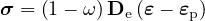
The main stress-strain law has the form
| (267) |
where σ is a vector of tractions and rotational components, ω is the damage variable and De is the elastic stiffness matrix, ε is a vector of strains obtained from displacement jumps smeared over the element length and rotational components and εp are the plastic strains.
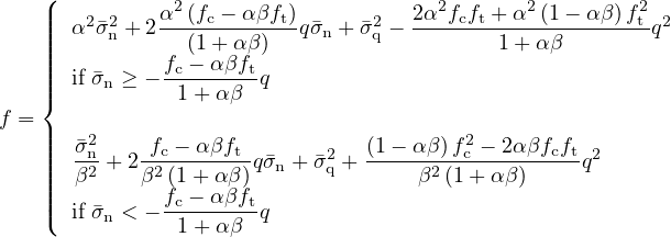
The plasticity part is based on the effective stresses and uses only a subset of the strains and stresses which are the normal stress σn and the two shear stresses σs and σt. The yield surface is composed of two ellipse which are arranged so that the transition of the two ellipses is smooth (Figure 14).
The resulting yield function f is
| (268) |
here parameters α and β are the slopes, and fc and ft are the strength parameters shown in Figure 14. The hardening function q controls the shape of the yield function.
The model parameters are summarised in Tab. 58.
| Description | Combined plasticity damage model for lattice elements |
| Record Format | latticeplastdam (in) # d(rn) # [ talpha(rn) #] [ calpha(rn) #] e(rn) # [ a1(rn) #] [ a2(rn) #] ft(rn) # fc(rn) # [ angle1(rn) #] [ angle2(rn) #] [ flow(rn) #] [ stype(rn) #] wf(rn) # [ ft1(rn) #] [ wf1(rn) #] [ ahard(rn) #] [ damage(in) #] [ sub(in) #] [ tol(rn) #] [ iter(in) #] |
| Parameters | - material number |
| - d material density |
|
| - [talpha] Thermal expansion coefficient. Default is 0. |
|
| - [calpha] thermal displacement expansion coefficient. Optional parameter. Default is 0. |
|
| - e modulus of the equivalent lattice material |
|
| - [a1] ratio of shear and normal modulus. Default is 1. |
|
| - [a2] ratio of rotational and normal modulus. Default is 1. |
|
| - ft tensile strength |
|
| - fc compressive strength |
|
| - [angle1] ratio of compressive and tensile strength. Default is 0.5 |
|
| - [angle2] ratio of compressive and tensile strength. Default is 0.5 |
|
| - [flow] ratio of compressive and tensile strength. Default is 0.25 |
|
| - [stype] softening types: 0-exponential, 1-bilinear. Default is 0 |
|
| - wf displacement threshold related to fracture energy used in both softening types. |
|
| - [wf1] displacement threshold related to softening type 1. Default is wf1=0.1 wf. |
|
| - [ft1] stress threshold related to softening type 1. Optional parameter. Default is ft1=0.15 ft. |
|
| - [ahard] displacement threshold related to fracture energy used in all three softening types. Default value is 0.1 |
|
| - [damage] flag to switch on and off damage. Default value is 1, which considers damage. |
|
| - [sub] maximum number of subincrementations in the plasticity part. Default is 10. |
|
| - [tol] tolerance for the newton iteration of the plasticity part. Default value is 1.e-6. |
|
| - [iter] maximum number of iterations for the stress return of the plasticity model. Default is 100. |
|
| Supported modes | 3dlattice |
This is an elasto-plastic model for slip between fibres modelled three-dimensional beam elements and lattice link elements. The theory of the model is described in the paper P. Grassl and A. Antonelli. ”3D network modelling of fracture processes in fibre-reinforced geomaterials”, International Journal of Solids and Structures, vol. 156-157, Pages 234-242, 2019. The model parameters are summarised in Tab. 59.
| Description | Slip model for lattice elements |
| Record Format | latticeslip (in) # d(rn) # [ talpha(rn) #] [ calpha(rn) #] e(rn) # [ a1(rn) #] [ a2(rn) #] t0(rn) # |
| Parameters | - material number |
| - d material density |
|
| - [talpha] Thermal expansion coefficient. Default is 0. |
|
| - [calpha] thermal displacement expansion coefficient. Optional parameter. Default is 0. |
|
| - e modulus of the equivalent lattice material |
|
| - [a1] ratio of shear and normal modulus. Default is 1000. |
|
| - [a2] ratio of rotational and normal modulus. Default is 1000. |
|
| - t0 limit of stress in slip direction |
|
| Supported modes | 3dlattice |
This is an elasto-plastic model for modelling the bond between two parts modelled with three dimensional lattice elements. The stress-strain law has the form
| (269) |
where σ is a vector of tractions and rotational components, De is the elastic stiffness matrix, ε is a vector of strains obtained from displacement jumps smeared over the element length and rotational components and εp are the plastic strains.
The theory of the model is described in the paper P. Grassl and T. Davies. ”Lattice modelling of corrosion induced cracking and bond in reinforced concrete”. Cement and Concrete Composites, Volume 33, pp. 918-924, 2011.
The model parameters are summarised in Tab. 60.
| Description | Bond model for lattice elements |
| Record Format | latticebondplast (in) # d(rn) # [ talpha(rn) #] [ calpha(rn) #] e(rn) # [ a1(rn) #] [ a2(rn) #] fc(rn) # angle1(rn) # ef(rn) # sub(in) # iter(in) # tol(rn) # |
| Parameters | - material number |
| - d material density |
|
| - [talpha] Thermal expansion coefficient. Default is 0. |
|
| - [calpha] thermal displacement expansion coefficient. Optional parameter. Default is 0. |
|
| - e modulus of the equivalent lattice material |
|
| - [a1] ratio of shear and normal modulus. Default is 1. |
|
| - [a2] ratio of rotational and normal modulus. Default is 1. |
|
| - fc compressive strength |
|
| - angle1 friction angle |
|
| - [ef] strain threshold to control hardening |
|
| - [sub] maximum number of subincrementations |
|
| - [iter] maximum number of newton iterations |
|
| - [tol] tolerance for newton method |
|
| Supported modes | 3dlattice |
This model combines a viscoelastic model, described in previous sections, with a linear elastic lattice material. Two material entries are used. One is for the viscoelastic lattice model and the other is for the viscoelastic model of choice.
The model description and parameters are summarized in Tab. 61.
| Description | Viscoelastic lattice model |
| Record Format | latticeviscoelastic (in) # viscomat(in) # d(rn) # [ talpha(rn) #] [ calpha(rn) #] e(rn) # [ a1(rn) #] [ a2(rn) #] |
| Parameters | - material number |
| - viscomat material number for viscoelastic model |
|
| - d material density |
|
| - [talpha] Thermal strain expansion coefficient. Default is 0. |
|
| - [calpha] Thermal displacement expansion coefficient. Default is 0. |
|
| - e Young’s modulus of the equivalent lattice material |
|
| - [a1] ratio of shear and normal modulus. Default is 1. |
|
| - [a2] ratio of rotational and normal modulus. Default is 1. |
|
| Supported modes | 2dlattice, 3dlattice |
This model combines a viscoelastic model, described in previous sections, with a damage lattice material model. Two material entries are used. One is for the viscoelastic extension of the damage lattice model and the other is for the viscoelastic model of choice.
The model description and parameters are summarized in Tab. 62.
| Description | Viscoelastic damage lattice model |
| Record Format | latticedamageviscoelastic (in) # viscomat(in) # timefactor(rn) # d(rn) # [ talpha(rn) #] [ calpha(rn) #] e(rn) # [ a1(rn) #] [ a2(rn) #] [ e0(rn) #] [ coh(rn) #] [ ec(rn) #] [ stype(rn) #] [ wf(rn) #] [ wf1(rn) #] |
| Parameters | - material number |
| - viscomat material number for viscoelastic model |
|
| - d material density |
|
| - [talpha] Thermal strain expansion coefficient. Default is 0. |
|
| - [calpha] Thermal displacement expansion coefficient. Default is 0. |
|
| - e Young’s modulus of the equivalent lattice material |
|
| - [a1] ratio of shear and normal modulus. Default is 1. |
|
| - [a2] ratio of rotational and normal modulus. Default is 1. |
|
| - e0 strain at tensile strength: ft∕E |
|
| - coh ratio of shear and tensile strength: fq∕ft |
|
| - ec ratio of compressive and tensile strength: fc∕ft |
|
| - [stype] softening types: 1-linear, 2-bilinear and 3-exponential. Default is 1. |
|
| - wf displacement threshold related to fracture energy used in all three softening types. |
|
| - [wf1] displacement threshold related to softening type 2. Default is wf1=0.15 wf. |
|
| - [e01] strain threshold related to softening type 2. Default is wf1=0.15 wf |
|
| - [bio] Biot’s coefficient. |
|
| - [btype] Type to consider how Biot’s coefficient changes with crack opening. |
|
| Supported modes | 2dlattice, 3dlattice |
This model combines a viscoelastic model, described in previous sections, with a plasticity damage lattice material model. Two material entries are used. One is for the viscoelastic extension of the plasticity damage lattice model and the other is for the viscoelastic model of choice.
The model description and parameters are summarized in Tab. 63.
| Description | Plasticity-damage viscoelastic lattice model |
| Record Format | latticeplasticitydamageviscoelastic (in) # viscomat(in) # timefactor(rn) # d(rn) # [ talpha(rn) #] [ calpha(rn) #] e(rn) # [ a1(rn) #] [ a2(rn) #] ft(rn) # fc(rn) # [ angle1(rn) #] [ angle2(rn) #] [ flow(rn) #] [ stype(rn) #] wf(rn) # [ ft1(rn) #] [ wf1(rn) #] [ ahard(rn) #] [ damage(in) #] [ sub(in) #] [ tol(rn) #] [ iter(in) #] |
| Parameters | - material number |
| - viscomat material number for viscoelastic material |
|
| - d material density |
|
| - [talpha] Thermal strain expansion coefficient. Default is 0. |
|
| - [calpha] Thermal displacement expansion coefficient. Default is 0. |
|
| - e Young’s modulus of the equivalent lattice material |
|
| - [a1] ratio of shear and normal modulus. Default is 1. |
|
| - [a2] ratio of rotational and normal modulus. Default is 1. |
|
| - ft tensile strength |
|
| - fc compressive strength |
|
| - [angle1] ratio of compressive and tensile strength. Default is 0.5 |
|
| - [angle2] ratio of compressive and tensile strength. Default is 0.5 |
|
| - [flow] ratio of compressive and tensile strength. Default is 0.25 |
|
| - [stype] softening types: 0-exponential, 1-bilinear. Default is 0 |
|
| - wf displacement threshold related to fracture energy used in both softening types. |
|
| - [wf1] displacement threshold related to softening type 1. Default is wf1=0.1 wf. |
|
| - [ft1] stress threshold related to softening type 1. Optional parameter. Default is ft1=0.15 ft. |
|
| - [ahard] displacement threshold related to fracture energy used in all three softening types. Default value is 0.1 |
|
| - [damage] flag to switch on and off damage. Default value is 1, which considers damage. |
|
| - [sub] maximum number of subincrementations in the plasticity part. Default is 10. |
|
| - [tol] tolerance for the newton iteration of the plasticity part. Default value is 1.e-6. |
|
| - [iter] maximum number of iterations for the stress return of the plasticity model. Default is 100. |
|
| Supported modes | 3dlattice |