Next: Miscellaneous Up: programmer Previous: XFEM module Contents
In the traditional FEA context, Element class is parent
class for finite elements. It maintains list of nodes, boundary
conditions (loads), integration rules, it keeps links to its
interpolation and associated material model and provides general
services for accessing its attributes, methods for returning its code
numbers, and abstract services for the evaluation of characteristic
components (e.g. stiffness matrix, load vector, etc.). In the proposed
IGA module, the individual NURBS (or B-spline)
patches are represented by classes derived from the base
IGAElement class which is in turn derived from Element
class. As a consequence, the B-spline patch is represented and treated as
a single entity, which returns its contributions that are localized into
global system of characteristic equations. This is important also in the
sense of slightly different handling of primary unknowns (see
Section ![[*]](crossref.png) ), compared to the standard FEA.
Moreover, it is quite natural because in a general case, degrees of
freedom (DOFs) on all nodes (control points) of the patch may interact
with each other.
), compared to the standard FEA.
Moreover, it is quite natural because in a general case, degrees of
freedom (DOFs) on all nodes (control points) of the patch may interact
with each other.
One of the fundamental issues, that has to be addressed at the element level, is the integration. The integration, usually the Gaussian integration, is performed over the nonzero knot spans. Individual integration points are represented by GaussPoint class. They maintain their spatial coordinates and corresponding integration weights. The individual integration points are set up and grouped together by base IntegrationRule class. For example, GaussIntegrationRule class, derived from IntegrationRule base, implements Gauss quadrature. An important feature is that an element may have several integration rules. This is very useful for the implementation of the reduced or selective integration, for example. The concept of multiple integration rules per element is extended in the present context of the IGA. The IGA_IntegrationElement class is introduced to represent the integration rule for individual nonzero knot spans, see Figure 5. Since it is derived from GaussIntegrationRule, it inherits the capability to set up Gauss integration points. The reason for creating a new class is to introduce the new attribute knotSpan, where the corresponding knot span is stored. This information is used in interpolation class to evaluate corresponding basis functions and their derivatives at a given integration point. Note that generally, the active knot span can be determined for each integration point on the fly whenever it is needed, but in our approach this information is stored to save the computational time. The IGA_IntegrationElement instances are set up for each nonzero knot span. The element integration then consists of a loop over individual nonzero knot spans, i.e. the loop over IGA_IntegrationElements and by inner loop over the individual integration points of the particular knot span.
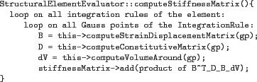
The individual IGA elements are derived from IGAElement class, derived from the base Element. The purpose of IGAElement class is to provide general method for initialization of individual integration rules on nonzero knot spans (represented by IGA_IntegrationElement class). The integration rules provide methods to create individual integration points in parametric space. An efficient implementation requires to map coordinates of individual integration points with parametric coordinates related to knot spans directly to knot vector based space. Specific elements are derived from the base Element (or IGAElement class), that delivers the generic element part and also from one or more classes implementing problem-specific functionality, see Figure 6. In the presented approach, StructuralElementEvaluator is an abstract base class, that defines the interface for structural analysis, which includes methods to evaluate mass and stiffness matrices, load vectors, etc. Some of the methods are already implemented at this level, such as stiffness matrix evaluation, based on declared abstract services (evaluation of strain-displacement matrix, etc.), which have to be implemented by derived classes. The example of the evaluation of the element stiffness matrix, which can be used by both classical and IGA based elements, is presented in Table 1 using symbolic code.
 |
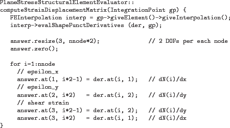
In the structural analysis context, classes derived from StructuralElementEvaluator implement desired functionality for specific types of structural analyzes (plane-stress, plane-strain, full 3D, etc). Provided that the element defines its interpolation (B-spline basis functions), it is possible to evaluate remaining abstract methods from StructuralElementEvaluator interface. This is illustrated in Table 2 on an example of the evaluation of the strain-displacement matrix for the case of plane stress analysis. Thus, when a new element is defined, it has to create its own interpolation and should be derived from Element class, which delivers the general basic element functionality and from one or more evaluators, implementing analysis-specific functionality. Such a design, based on decoupled representation of element interpolation and problem specific evaluators, has several advantages. It allows to define problem specific methods only once for several elements with different geometry and interpolation and allows straightforward implementation of elements for multi-physics simulations.
The description of the element interpolation is encapsulated into a class derived from FEInterpolation class which defines the abstract interface in terms of services that evaluate shape functions, their derivatives, jacobian matrix, etc. at given point. In the frame of presented work, theBSplineInterpolation class has been implemented. Each finite element has to set up its interpolation and provide access to it. This is enforced by general Element interface, that requires to define the method for accessing element interpolation. The abstract FEInterpolation class interface is essential, as it allows to implement problem specific element methods already at the top level (like the evaluation of element interpolation or strain-displacement matrices). An efficient implementation should profit from the locality of individual interpolation functions which have limited support over several consecutive knot spans. Therefore methods declared by FEInterpolation class evaluating values of interpolation functions or their derivatives return the values only for those, that are nonzero in actual knot span. This enables to compute characteristic element contributions on a knot span basis efficiently. For each individual knot span, the contributions are computed only for generally nonzero shape functions and then are localized into element contribution. The mask of nonzero shape functions for individual knot spans can be evaluated using giveKnotBasisFuncMask service declared by FEInterpolation and really provided by BSplineInterpolation.
Borek Patzak 2018-01-02
![\includegraphics[width=0.7\textwidth]{class_IGA__IntegrationElement_mod.eps}](img25.png)
![\includegraphics[width=0.7\textwidth]{class_BsplinePlaneStressElement_collaboration.eps}](img27.png)